TOWER SHADOWING
By
Ira Wiesenfeld, P.E.
INTRODUCTION
A [few years ago], I was contacted by a municipality who had just upgraded their single-site 800 MHz enterprise public safety trunking radio system to a two-site simulcast system. Instead of getting more range on the new system, the range was reduced considerably and the cities sharing this system were in desperate need of help.
This system was designed by one of the major manufacturers in the business. The city did choose the towers that were available and must be used, and the manufacturer used that fact as the basis for the system needing more towers to be effective.
In trying to solve the problem at hand, I did make a detailed analysis of what it would take to fix the problem. I wrote a 24-page report on the system and how to fix the problem, and the manufacturer wrote a 68-page rebuttal that did not address the problem but suggested that my analysis was wrong, and the city just needed more sites.
My initial diagnosis of the problem was that tower shadowing was blocking the radio signals, and the engineers from the radio manufacturer and from the antenna manufacturer immediately accused me of being wrong. The radio manufacturer had convinced the city that I was wrong, and more sites were needed. This required me to conduct a thorough study of the system to prove to the city and the radio manufacturer that they did not install the antennas for optimum coverage. I was hindered in supporting my point of view because there is little literature that is published that explains tower shadowing. Hopefully, this article will aid others with similar problems.
Every day since the system went on the air, hundreds of police, fire, EMS personnel, and other city employees were putting their personal safety in jeopardy due to the poor radio coverage in their jurisdictions. I have worked in public-safety communications for over four decades, and I know that this system was a danger to those people who put their dedication to others before their own needs. In the end, my only concern is for the users of the system and not the “SITYS” (SEE-I-TOLD-YOU-SO).
This article is written to explain to engineers, technicians, and radio system managers what tower shadowing is, and how to use it properly.
ANTENNA PLACEMENTS
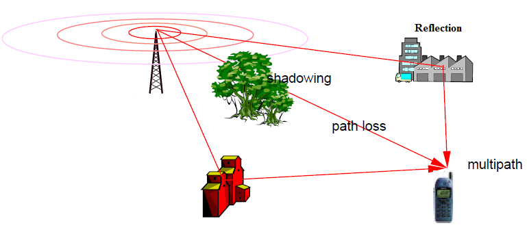
In every radio system, the antenna is the most important component that sets the range of the system. The height of the antenna sets the theoretical maximum range, but the actual range is usually reduced by obstructions, such as trees and foliage, buildings, hills and ground elevation obstruction. In addition, the mounting location on the tower or rooftop has a lot to do with the range. Sometimes, engineers use the tower shadow to protect against interference to and from other systems. This section will look at the effects of antenna placement of the mounting structure in relation to the antenna’s performance.
The ultimate place to mount an antenna is the top of a tower with no other antennas near the antenna. In real life, most towers have multiple antennas at the top, and since the side of the tower has plenty of room, there are as many antennas in use on the sides of towers as there are on the top of the towers.
 The radiation pattern of a simple omnidirectional antenna, a vertical half-wave dipole antenna. In this graph the antenna is at the center of the "donut," or torus. Radial distance from the center represents the power radiated in that direction. The power radiated is maximum in horizontal directions, dropping to zero directly above and below the antenna. Added by Brad Dye (August 2021) |
The lone antenna at the top of a tower will have a 360-degree radiation pattern called OMNI-DIRECTIONAL. If you place any object near the antenna, whether it is another antenna or the side of a tower, the pattern will then have an offset pattern. The pattern can be predicted and is usually shown in the catalogs from the antenna manufacturers as how the pattern is distorted from the tower.
The same goes for buildings rooftops. In fact, buildings have an advantage in that each antenna has less distortion from the other antennas, as there is usually enough room at a building site as to not have the antennas crowding each other and causing severely distorted patterns. There is also less attenuation on the coaxial transmission line on a rooftop location for most sites.
In some systems, it is desirable to have the antenna have a directivity so that all of the power to and from the system is in one or two directions, and the directions where the signal is not needed or wanted is reduced substantially. Some of the antennas that are designed to have a concentration of power in one direction and have substantial attenuation in other directions include:
- Yagi
- Corner Reflector
- Cardiod
- Elliptical
- Offset
- Parabolic Reflector
If you have another system on the same channel (called co-channel) and you want to reduce the interference with this other system, you would normally use the tower to shade the signal in the direction of the co-channel system and this normally does fix many co-channel problems.
You can also use the tower to shield one system from the other on the same tower by placing the antennas on opposite sides of the tower and letting the tower shadow keep each signal down by 20 dB (x 100 power) or more. You can also use the vertical separation by placing the antennas vertically apart which provides a great deal of isolation from each other electrically, usually in the order of 40 dB (X 10,000) or greater. In these last two examples, the tower shadow or vertical separation is used to enhance the operation of the system.
In the system for this municipality, the tower located in the north part of the territory had the transmitting antenna mounted on the north side of the tower. This cast a large shadow to the south, where most of the users are located. The south tower had the receiving antenna on the south side of the tower, and all the users are located north of this tower. In addition, the transmitter antenna for the south tower was mounted on the west leg, and the cities to the east had minimal coverage from this site. In summary, more than 60% of the cities in this system were affected by the tower shadows. One of the cities was in the shadows from both sites, and their radio coverage was so bad, the police department had to use cellular telephones for keeping up with their field units.
A second city called just a [few years ago,] and again, the initial diagnosis after making a field visit to the municipality was that the tower shadow was the problem here. Just as the radio manufacturer denied the problem in the first case, the other manufacture had the exact same reaction here. Again, I made a detailed study of the signal strength at exactly 1 mile from the tower at 30-degree intervals, and the results were quite revealing as to the problem. The area where the town was having problems was exactly the area that was found to be shadowed by the tower. The first city uses the 800 MHz band, while this second city uses the 460 MHz band. This just proves that the problem with shadows is not band specific.
BASIC PHYSICS
The one thing about radio waves is that they always obey the laws of physics. This fact allows engineers to be able to very accurately predict how the radio waves will perform. The performance can then be measured, which is called EMPIRICAL measurements, and the results are always the same. In fact, if the field measurements do not match the predicted values, you normally send out a technician or engineer to find out why the measured values do not equal the predicted values. Once the problem is found, the predicted values will match the measured values.
In the first system that I was looking at, the predicted value for the field strength at 1 mile was supposed to be -46.5 dBm, and the measured value was -47.0 dBm. This difference is within the specification of the accuracy of the spectrum analyzer that was being used. In the shadow areas, we measured -66 dBm at 1 mile when the antenna was on the north side of the tower. When we went back to the exact same spot after we moved the antenna to the southwest side of the tower, the signal rose 21 dB to a -45 dBm. This is 120 times (12,000%) increase in signal strength power. Again, we were within the measurement accuracy of the spectrum analyzer between the predicted value and the measured signal strength at that site. Once the shadow was controlled, there was an immediate improvement of coverage for the cities involved.
In the second system, the predicted signal strength was –42.0 dBm, and the measured signal was also –42.0 dBm at the points where there were no obstructions of the clear Line-Of-Site path to the 1-mile mark from the tower. In the tower shadow obstructed areas, the signal was down at least 20 dB, which translates to 1/100 of the power getting out in the direction of the shadow area.
Some of the laws of physics that we will discuss here that are pertinent to predicting the signal strength of the radio waves include:
- Inverse Square Law
- Free Space Attenuation
- Phasing
- Antenna Gain
- Downtilt
The Inverse Square law says that the field strength will drop by the square of the distance. In simple terms, if you measured a value at a given point, and you double the distance, you will drop the field intensity by 1/4. If you tripled the distance, you would drop the field intensity by 1/9.
Radio engineers have a formula that allows them to calculate the field intensity of a signal using the formula for Free Space Attenuation. This formula is:
ATTN (dB) = 36.6 + 20 X LOG (Frequency in MHz) + 20 X LOG (Distance in Miles)
This formula holds true if you have Line-of-Sight propagation.
Radio signals can bounce off objects and if they arrive in phase from the source to the receiver, the signals will add and give gain. If the signal arrives out of phase, it can cause the field intensity to drop significantly, depending upon the amplitude of the out of phase signal and the phase relationship to the direct signal.
In some systems, the antenna can be so high in elevation that the main signal can literally pass over the intended coverage area. You will see this in parts of the country where a mountain top site can be thousands of feet above the area you are trying to cover. When this is the case, you can use beam tilt to bring the signal down to have better coverage in the desired coverage area. If your antenna height is less than one thousand feet above the desired coverage area, you do not want to use beam tilt.
When an engineer designs a system, all the factors go into the selection of the antenna site, antenna mounting, antenna type, coax feedline attenuation, plus the transmitter power and other pertinent factors to meet the coverage requirements of the system being designed.
MANUFACTURER DIAGRAMS
Most of the major antenna manufacturers have diagrams that show how the side mounting of an antenna to a tower distorts the omni-directional pattern of the antenna. These are usually drawn as polar graph diagrams based upon an omni-directional antenna. If you have an antenna that has an offset pattern, then you must combine the antenna offset pattern with the distortion pattern to see the actual pattern that would be present for that antenna with a side mounting.
Some manufacturers do not acknowledge shadowing, but it does exist and does need to be part of the system design.
COMPUTER MODELING
 Side mounted, vertical, folded dipole. Added by Brad Dye (August 2021) |
The effects of a tower on an omni-directional antenna will be influenced by the size of the tower legs, the size of the tower face, how far the antenna is from the tower, where the antenna is in relation to the legs vs. the face of the tower, what frequency the antenna is operating on, how much coaxial transmission line is on the tower at that level, and what is the free space radiation pattern of that same antenna.
The formula to do this computing is quite complex, has some constants that were determined by empirical measurements, and will take quite some time to set up on a computer.
One of the top engineers in the world on antenna patterns has developed a computer software program that allows the engineer to input into the data input fields the pertinent antenna and tower parameters, and the output will be a graph showing the detail pattern and numeric attenuation for a given antenna on a given tower. In fact, most of the antenna manufacturing companies have used his software to show the offset patterns caused by towers.
The name of the engineer is Arthur K. Peters, and he sells this program called Obspath for under $1,000.00. If you tried to duplicate his work, you will spend many weeks of programming time to match his program. I have not collaborated with Mr. Peters, so he does not endorse this mention of his name or is in any way connected to him. I have known of Mr. Peters since my early days in radio, but our paths have never crossed.
EMPIRICAL MEASUREMENTS
Radio system performance can be measured with the test equipment available, and the measured performance should match the predicted performance if everything is working properly. This section will detail some of the tests and some of the anomalies that will be seen during normal radio system observation.
Before making any field measurements, you should verify the transmitter power output, frequency, modulation levels, and do a Frequency Domain Reflectometery sweep of the antenna and coaxial system. (See MRT Magazine, April 2003 for an explanation of this technology if you are not familiar with it.) (https://urgentcomm.com/2003/04/01/antenna-system-troubleshooting-simplified/)
You can then make a starting point for checking a system’s range by drawing on a map the radials from the tower or building every 30 degrees or every 45 degrees, and you have these radials exactly 1 mile in length. You will find that on many systems, the signal strength will not match the predicted value, but you can move your test set antenna by just a few inches from the set point on the map and the signal strength will move by as much a 15 dB. There are two different phenomenons occurring to cause this variation in signal strength.
The first item that can cause a variation in signal strength is called RAYLEIGH FADING. This is where the signal strength will follow a pattern of peaks and valleys as you follow a radial path to or from the tower. The peaks will occur every 1/2 wavelength, and the valleys will occur 1/4 wavelength in distance past each peak. All radio systems have this characteristic. Therefore you can move a few inches with your Walkie-talkie or mobile unit and go from a weak signal to a strong signal. There is nothing wrong with your system, as this is a normal part of every radio system.
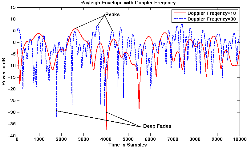
Added by Brad Dye (August 2021)
The second item that causes radio signals to have peaks and valleys is found on antennas that are not top mounted by themselves on a tower. When an antenna is side mounted on a tower or has other metallic objects where the signal can bounce off the object, there will be reflections. These reflections can arrive in-phase at the reception point, and the signal strength will be stronger than normal. When the signal arrives out of phase, the signal strength will be lower than normal. This will occur on every radio system where the antenna has metal objects near where the signal can bounce off the object. The overall effect is called SPOKING.
If you think that you are being affected by tower shadowing, then draw your radials every 2 degrees in the area that you believe is being shadowed. You will immediately see if shadowing is a problem with the results of this empirical study.

Added by Brad Dye (August 2021)
Radio signals do not propagate outward from the antenna in straight lines as this drawing might suggest. These equal-length radial lines indicate distant points for measuring the field strength of the signal which wiill then illustrate the amount of tower shadowing.
| Radio waves propagate outwards from an omnidirectional antenna like the ripples created when a small rock is dropped into still water. | |
|
 |

Added by Brad Dye (August 2021)
EFFECTS ON REAL SYSTEMS
In radio and electronics, the numbers are listed in Decibels, but not everyone understands these relationships. Below is a brief explanation of decibels.
Numbers can be expressed in two forms. The first is the number itself. The second is how much the number 10 must be raised by an exponent to get that number. The examples below will help you understand this:
| EXAMPLE | ||
| 100 | = | 102 |
| 1000 | = | 103 |
| 0.01 | = | 10-4 |
| 2 | = | 100.301 |
| 3 | = | 100.4771 |
Logarithms are useful because extremely large and extremely small numbers are easier to express. The difference between the two numbers is not related to the numbers themselves. The advent of the scientific calculator has made the use of logarithms very easy. There are two types of logarithms, natural and common. The common logarithm is based on powers of 10 and is calculated using the key LOG and is different than the natural logarithm, which is calculated by using the LN key on the calculator. The LN key will not be used in these applications.
Gains of amplifiers, loss of power, audio levels, earthquakes and many other quantities are expressed in numbers based upon logarithms. Human senses such as light intensity, hearing and pain intensity are also measured by the body logarithmically. The common level expressed in decibels is based upon a mathematical formula based upon logarithms.
DECIBELS
Decibels are the unit of relative measure used throughout the radio world. The following formulas are used for calculating decibels:
| POWER | ||
| DBPower | = | 10 x LOG (POUT / PIN) |
| DBVoltage | = | 20 x LOG (VOUT / VIN) |
If you always have the OUT divided by the IN level, the following will always hold true:
A positive number represents GAIN.
A negative number represents LOSS.
If the Input and Output are the same, the gain will be 0 dB.
EFFECTIVE RADIATED POWER
A radio transmitter system consists of the transmitter, antenna peripheral equipment, coaxial line loss, connector loss and antenna gain or loss. The EFFECTIVE RADIATED POWER (ERP) is the amount of power that would be the equivalent if a transmitter was placed on the tower with a unity gain antenna.
The transmitter power, less the losses, added with the gains, gives the ERP.
Power (ERP) = Power (Transmitter) – Power (Losses) + Power (Gains)
dBm
dBm is a unit of ABSOLUTE POWER, where dB is a relative number. The following chart will help show this:
| 0 dBm | = | 1 milliwatt |
| +30 dBm | = | 1 Watt |
| +60 dBm | = | 1000 Watts |
| -30 dBm | = | 1 microwatt (µW) |
| dBm = 10 Log [(POUT) / 1µV] | ||
When you are working in radio, the impedance is 50 Ω (Ohms).
When you are working in telephony, the impedance is 600 Ω (Ohms).
Either way, the power levels or voltage levels are the same.
| POWER RATIOS AND DECIBELS | ||
| X2 | = | 3 DB |
| X4 | = | 6 DB |
| X10 | = | 10 DB |
| X100 | = | 20 DB |
| X1000 | = | 30 DB |
| X ½ | = | -3 DB |
| X 1/10 | = | -10 DB |
| VOLTAGE RATIOS AND DECIBELS | ||
| X2 | = | 6 DB |
| X4 | = | 12 DB |
| X10 | = | 20 DB |
| X100 | = | 40 DB |
| X ½ | = | -6 DB |
| X 1/10 | = | -20 DB |
Now that we understand a little bit about Decibels, let us now differentiate between the common uses and misuses of this term.
When working with radio signals, the levels can be extremely large or extremely small, and as a result, the use of Decibels is necessary to express these levels. The following four sections will help in separating the uses of the term dB.
dB |
When you use the term dB, you are only comparing one signal value to another signal value. When looking at a filter loss, amplifier gain, or antenna gain or loss, then the use of the term dB is the correct choice. |
dBm |
dBm is an absolute value. If you had a 100-watt transmitter, that would equate to a +50.0 dBm level. If you had a 2-microvolt signal, that would equate to a -100 dBm signal. If you have a 0.5 microvolt (µV) signal, that would be a -112 dBm. Most two-way radio receivers operate in the range of -113 dBm to -124 dBm, while most wireless LAN receivers operate with a sensitivity level of -70 dBm to -100 dBm. Wi-Fi systems with extended range operate with a sensitivity of -130 dBm. GPS receivers have a sensitivity of -135 dBm. Most Communications Service Monitors have a sensitivity of -100 dBm. |
dBd |
dBd is used when expressing antenna gain based on the difference between the signal of a dipole antenna verses the signal gain from the given antenna. Antennas derive gain by redirecting the signal from undesirable or non-useful directions to more useful directions. This gain can be measured or calculated and is expressed in dBd. |
dBi |
As a ruse to make uninformed engineers and technicians think that an antenna has more gain than it really has, some manufacturers started using the term dBi to represent the gain over an ISOTROPIC point in space, which exists in theory only. There is a 2.1 dB difference between a dBd and a dBi. An example would be a 13.0 dBd gain antenna would also have a 15.1 dBi gain. In reality it is the same antenna. |
OBSTRUCTIONS
A single tree can cause a signal to drop from 0 dB to as much as 20 dB (x 100). Likewise, a building can have an effect of 0 dB to more than 40 dB (x 10,000), depending upon the materials and metal content of a building. A hill or drop in elevation can have enough attenuation to possible kill the signal.
Added by Brad Dye (August 2021)
There are computer propagation programs on the market that can predict what the coverage will be, including the effect of the obstructions and ground elevations. When the radio manufacturers or radio dealers run their programs, they usually are very conservative in their predictions because they normally have a motto which is UNDER PROMISE and OVER PERFORM. This has two good effects for them. Firstly, they always deliver more in the system performance that they had the customer expecting. Secondly, the dealer or manufacturer can sell more equipment, because their studies indicated that the system required higher towers, more sites, or both. As the end customer, you want the actual coverage studies, as you probably have more spending requirements than you have a budget for if you are like most organizations. Even though the manufacture or radio dealer is willing to provide you propagation studies for free, this can sometimes cost you more in the long run. You might want an independent study if you are making a large investment or if you have a mission critical situation. Spending a few hundred dollars can save you thousands of dollars in the long run.
RF INTERFERENCE
If the range of a system that is less than the expected predictions have, it is usually due to RF Interference. The source of the interference might be from your own system, somebody else’s system, or from a myriad of electromagnetic energy sources that are beyond the scope of this article to explain. In short, many times the range is deficient, but the hardware in your system is working properly.
If you suspect interference, there are tests that can be performed to confirm that this is the case. If the tests do confirm that RF Interference does exist, then there are quite a few options that can be followed to correct these problems. Please note that not every interference problem can be corrected without somebody having to move one of the radio systems or the redesign of one of the associated components.
MOBILE AND PORTABLE UNIT PERFORMANCE
In some cases, the problem may or may not be caused by the infrastructure radio system. If you have quite a few mobile units and portable units not meeting factory specifications, you will think that your system does not work correctly, but, you have multiple mobile units and portable units not working making you think that it is the fixed equipment in trouble.
Mobile units need to have good antennas and installations. I had a Sheriff’s Department using “INMATE RADIO SERVICE COMPANY” (IRSC) which was the polite way of saying the prisoners who were convicted thieves and drug dealers were the cheap labor. The Sheriff was using these people to install the radios into the squad cars. The local radio shop that had formally been maintaining the old system had told the fleet service manger to be sure and use “ALL” of the silicon lubricant that came with each antenna and fill the antenna connection fitting with the silicon to keep the moisture out of the connection after he did not get the bid for the new system. I am sure that he was laughing all the way home over this prank. The silicon is used on the part of the mount to keep moisture out of the vehicle but is not supposed to have any contact with the antenna radiator that uses a pressure fit to make the RF connection to the antenna rod. The IRSC employees used every drop of the silicon into the mount, which made an insulator between the supplied NMO mount center conductor button and the antenna rod. The range of the new system was less than 1 mile for the sheriff’s squad cars, but over 30 miles for my car, my walkie-talkie, and the mobile units that were installed anywhere other than the sheriff’s dolly port.
To compound the problem, the radio dealer that did get the bid for the equipment had told IRSC that they did not need to solder the PL259 connectors that went into the back of the radios. There were shorts and opens in over half of the radios installed by IRSC and other shops that had listened to this dealer. You CANNOT take a shortcut on the installation and expect things to work as the engineer designed the system.
It took almost 6 months to correct all the fleet installation problems with the mobile units. It is much easier to just put the fleet equipment in properly than to chase installation problems.
When you trade in a squad car or other emergency services vehicle, you should buy a new antenna and cable. The $30 to $50 that you save will eventually cost you more than that when you have problems later down the road. Hopefully, nobody gets injured because of the decision of a bookkeeper or accounting manager. The radio is truly the lifeline for public safety personnel and used antennas on an installation should NEVER be allowed.
Just as mobile units have their problems, so can portable radios. The batteries should have sufficient energy to last though an entire shift. For police departments this might be 8 hours, or it could be 12 hours. For fire personnel, many of them operate 24 hours straight, and they might need more than one battery per shift. The batteries are only good for 500 recharge cycles, so most batteries should be replaced after two years of use. I have been at agencies that use their batteries for three to six years, yet they wonder why the radio system just does not work like it used to. Also, a portable radio worn on someone’s belt will have shadowing and antenna detuning. (See MRT Magazine November 2007 for further information on this problem.) [MRT Magazine is now IWCE's Urgent Communications so this article is probably not online anymore.]
Just because a radio system is not performing like it is supposed to or once did, the problem may not be in the fixed infrastructure equipment. Always consider the mobile and portable radios as a part of the “system”.
CONCLUSION
Tower shadowing can and does occur on many radio systems. The effects can be predicted and used to enhance the system performance if this factor is known and controlled. If your system is not performing as expected, this article has also explained some of the factors that could possibly be causing your system to not work as the engineer designed it. Whether you have commercial radio system, a public safety system, or even an amateur radio system, the effects of shadowing are real and can be overcome. If you do have tower shadowing, just make sure that it is in a direction where the shadow does not affect the system performance for the primary territory that you are trying to cover. [I] hope the above information has helped to clear up any confusions or misunderstandings of Radio System performance and or expectations.
A side-mounted omnidirectional antenna on a tower. Vertical view from the top down — illustrating how shadowing is created by the tower, partially blocking the signal. This section added by Brad Dye (August 2021) |

Ira Wiesenfeld, Principal Engineer — Ira Wiesenfeld and Associates
Ira Wiesenfeld, P.E., is a consulting engineer who has been involved with commercial radio systems since 1966. He has spent time working in the broadcast, two-way, mobile telephone, paging, microwave, military, and public safety radio systems, and has consulted with most of the major manufacturers in the radio industry. Ira is the author of Wiring for Wireless Sites, available from Delmar Thompson / Prompt Publishing (www.electronictech.com).
Ira has a BSEE from Southern Methodist University in Dallas, Texas; an FCC General Radiotelephone Operator License; is a Senior Certified Radio Technician from the Electronics Technicians Association - International; and is a licensed Professional Engineer in the State of Texas. He holds an Extra class Amateur radio license WA5GXP. He has lived in Dallas, Texas his entire life. Ira can be reached by e-mail at iwiesenfel@aol.com or on the web at https://www.iwa-radio.com The original publication of this article was in MRT Magazine: |