![]()
| Precise Frequency Locking for the RFSpace SDR radios |
![]()
Precise Frequency Locking for the RFSpace SDR radios Dave Powis, G4HUP The RFSpace SDR-IQ and SDR-14 are excellent wideband receivers, and can be used with SpectraVue, Winrad and Linrad SDR software. A new application, SDR Radio, should be available for them in the very near future. Both receivers have a simple hardware front end, which is basically an ADC, converting the RF to a data stream, connecting to the PC over USB. The significant difference between the two is that the -14 is capable of converting and displaying the entire 30MHz at once, whereas the –IQ can handle up to 190kHz — the limitation seems to be more in the USB data handling rate rather than the front end hardware. Whichever receiver you have, there may be applications where the internal clock is not precise enough — this is especially likely to be the case if you are trying to capture very narrow bandwidth sub-noise signals which require long term integration — as they are sub-noise level, there is no trace on the waterfall, or visible component on the spectrum for you to confirm that you have the frequency precisely tuned. Typically, some of the Deep Space Network signal reception requires this type of operation. The standard internal reference is a 66.667MHz oscillator — but fortunately, this is easily disabled in both variants, and an external signal can be fed in, in its place. An accurate 66.667MHz signal can also be generated easily from a standard 10MHz reference using Direct Frequency Synthesis. This is method of frequency generation which relies on multiplication, division and mixing, with no ‘locked loops’ to generate noise or go out of lock. It also has the advantage that the only oscillator is at 10MHz, where high quality oscillators with low phase noise are readily available — producing a low-phase noise VHF oscillator is well beyond the capabilities, and test equipment, of most amateur electronics enthusiasts! 10MHz Reference Oscillators Suitable reference oscillators are readily available as complete GPS disciplined systems, such as the second-hand HP/Symmetricom Z3801A and other models, the Trimble Thunderbolt, the G3RUH GPSDO and many home/amateur produced variants, such as VE2ZAZ and the Brookes Shera design. Even if a full GPS-DO system is not practical or affordable, 10MHz reference OCXO’s are fairly easy to come by, and often of very good quality. Due to their ubiquity as reference sources, a lot of effort has been put in by manufacturers, and it makes good sense to take advantage of that! A reasonable quality OXCO, running ‘stand alone’ (i.e. not automatically controlled by any reference such as GPS) will still make a very good reliable source. Ideally it should be left permanently running, and if checked and adjusted against a source such as WWV every month or so will settle down to be a very good accurate source. I strongly recommend using good old fashioned Lissajous figures as an easy to use method for the comparison process! A 66.67MHz DFS Fig. 1 shows the block functions of a 66.67MHz DFS. This will be used to explain the circuit operation. Fig. 1 – Single loop DFS solution for 66.667MHz The 10MHz input is split into two – one side goes through the x7 VHF multiplier diode, up to 70MHz. The other signal is divided by 3 to give 3.33MHz – this is then low pass filtered to recover the sine wave, so that it can be mixed with the VHF signal. At the output of the mixer there will be both 66.67 and 73.33MHz components present. An LC bandpass filter is used to select the wanted side frequency (in this case 66.67MHz), and then a 3 stage VHF crystal ladder filter completes the ‘clean-up’. Although crystals are quite expensive these days, a very economical solution is available by using miniature tubular resonator crystals. Having compared their performance with standard HC49/U crystals, it is definitely not as good – but the cost ratio is about 40 to 1 – you can accept some degradation in output spurii (approx 10dB) for that benefit in this application!
Fig.
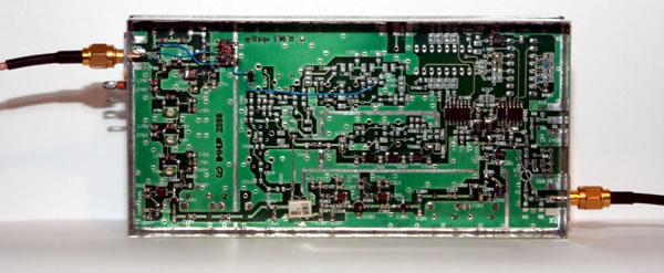
2 - Underside view of the completed 66.667MHz
DFS. Since the SDR radios use the signal directly to clock the DDS that runs the ADC timing, having spurii at -55dBc is not such a significant issue as it would be were the output to be multiplied up as the LO for a microwave system — the normal application of DFS’s. For those applications I like to see the spurii better than -65dBc. In addition to the economy version crystal filter, there is another modification to the standard design needed for driving the SDR receiver — the output needs to be a square wave, and it must not exceed 3.3 v, since that is the Vcc used in the SDR boxes. A squarer circuit is used, based on 74AC logic, to convert the sine wave output at 66.67MHz to a square waveform for the SDR-IQ. The circuit is due to David Smith, VK3HZ, and has a 74AC14 chip, powered from a 3V3 regulator. I had problems confirming that the output was indeed a square wave, since a single inverter will not drive a 50Ω load, so in my implementation I have paralleled three sections for the output — this is not required for the SDR drive, but did at least enable me to see the output correctly on a high speed 50Ω scope! After building the prototype ‘dead-bug’ style (see Fig. 2), I initially used a small daughter board to hold these extra components inside the DFS, as shown in Fig. 3.
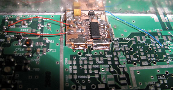
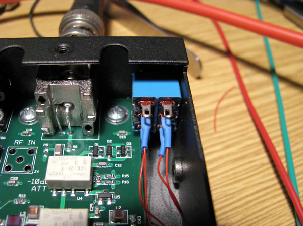
Fig. 3 – Close up of the Squarer circuit board inside the DFS 66.667MHz Blue lead to right is +5v DC, input and output signal leads to left. Further experimentation has shown this to be an inappropriate location, as the daughter PCB is directly above the main regulators of the DFS, which run fairly hot. In high ambient temperatures the squarer function can become unreliable, causing the SDR to crash. Since there is no other convenient location within the DFS housing, I now recommend mounting the squarer outboard of the DFS in a small separate tinplate housing, which removes this weakness. An alternative is to mount a small fan on the DFS casing to create airflow through the box — see http://www.braddye.com/gps_do.php for an example of this approach. Connecting the LO Signal into the SDR receivers SDR-IQ In my own unit I have also installed a small switch on the rear panel, as well as the SMA connector for the external LO signal, as in Figs. 4 and 5 below. This allows me to switch between internal and external LO operation, and thus allows the SDR to be used when there is no frequency locked LO available. Note that SpectraVue must be closed and restarted when changing from one LO source to the other.
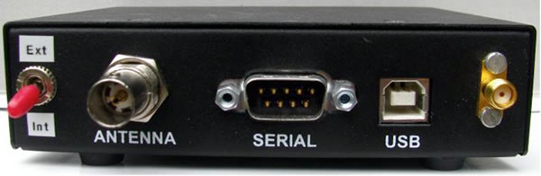
Fig. 4 – Close up view of the LO switch installation in the SDR-IQ
Fig. 5 – View of SDR-IQ rear panel, showing LO switch and input connector SDR-14 No changes are needed in the software for either receiver, since all we have done is stabilise the 66.667MHz by frequency locking, not change it in any way. In use there is no difference in operation — except that even for your most demanding applications you will have absolute confidence that your frequency setting is correct! More information on this and other versions of the Flexible Direct Frequency Synthesiser can be found on my web-site at http://g4hup.com |
![]()
Dave Powis, G4HUP, SK Sad news that Dave Powis, G4HUP became a silent key on 9 February. Dave was a well-respected tutor and mentor and a very active member of several radio clubs, mentoring many candidates to gaining their amateur radio licences. He joined the Examinations Standards Committee in 2007 and spent much of 2016 working with the Exams Group on revising the licence syllabuses. Late in 2016 he became RSGB Exam Standards Committee Chairman and was just beginning to bring his newest ideas to bear. He also was well-known for the excellent surface mount soldering classes at the RSGB Convention in recent years. Our thoughts are with his family and many friends at this difficult time. [source] |
![]()
73 DE K9IQY |
Wireless Messaging News
|
 |
 |
| Skype: braddye Telephone: 618-599-7869 E–mail: brad@braddye.com Wireless Consulting page Paging Information Home Page Marketing & Engineering Papers |
 |
WIRELESS MESSAGING |
![]()
| Why Paging Technology is the Best Solution for Mass Alerting |
![]()
| Home Page | Directory | Consulting | Newsletters | Free Subscription | Products | Reference | Glossary | Send e-mail |